In this article I will explain how RenderWare projects vertices. There is an excellent article on the topic of projection on songho.ca which I very much recommend checking out. Mine will be similar but explain RW's way of doing it specifically.
Vertices are transformed from world space to camera space by the View Matrix that is stored in a RwCamera. There is a short paper in the RW SDK that explains how it's build, but it is not as detailed as it perhaps could be. This article can be considered an explanation and illustration of the paper.
N.B.: this matrix is not actually used for rendering on all platforms. For D3D and OpenGL in particular separate matrices are constructed by the platform specific RwCameraBeginUpdate functions. The matrix here constructed is used on the PS2 but modified a bit by the VU1 code.
RW's View matrix is the concatenation of the inverse camera matrix and the projection matrix. The inverse camera matrix is simply the inverse of the RwCamera's RwFrame matrix but with x negated to give us left handed coordinates. Transforming with this puts the camera at the origin with the x axis going right, y up, and z forward.
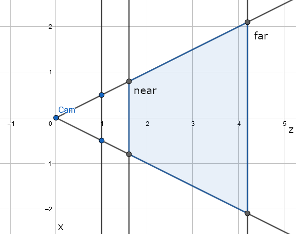
To project vertices, we have to define a camera frustum. All vertices inside this frustum will be visible on screen, all outside will not. A frustum is a clipped pyramid, so let's start with the pyramid first. The apex of the pyramid is the position of the camera, i.e. the origin. We also define a rectangle on the z-plane centered at (0, 0, 1), its half-width and half-height are the view window in the RwCamera. Finally the pyramid is clipped at z=near and z=far. This is how the frustum looks when looking down y:
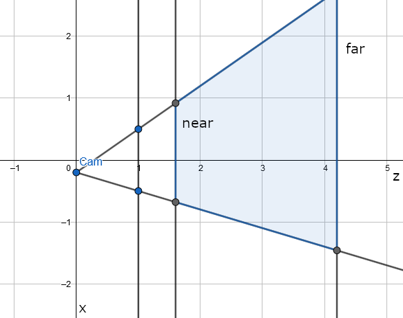
But this is not the whole story. There is also the view offset, which is applied to the apex to give an oblique pyramid (or frustum). The view window itself is undisturbed by this, it stays centered at (0, 0, 1). With a small positive offset in x, the frustum now looks like this:
Finally to project a point we calculate its coordinates in the view window. Every point that is inside the frustum will be projected onto the window, everything that is outside the frustum in x or y will not. Points outside the z range [near, far] will be problematic but we'll deal with that later. Calculating the projected coordinates is very easy. For any point let xcam be its x coordinate in camera space and xproj the x coordinate of the projected point. From the ratio of similar triangles we know that xcam/zcam = xproj/1. Hence we simply have to divide xcam by zcam. The same applies to y.
Our goal is to map the view window to the square (0,0,1) (1,1,1) in camera space. Every step in this is done by a matrix transformation as explained in the RW paper mentioned above.
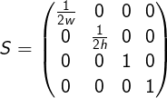
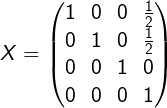
First of all we'll have to apply the view offset to put the camera at the origin again. To place the camera at the origin is a simple translation but we also need a shear to express the fact that the camera is not centered behind the view window. Since we do not want to disturb the z=1 plane, the shear and translation have to cancel each other out at z=1. Combining this gives us the first matrix:
Next we scale the view window to a unit square centered at (0, 0, 1). Since the dimensions stored in RwCamera are actually half of the width and height, we have to divide by twice the values. For this simple scale we get:
Up until now the w value has always been 1. To do the projection we let it be equal to z and divide by it later. We also have to flip y because it goes down in screen space. Thus we get:
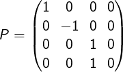
Finally we translate the view window such that it is no longer centered on the z-axis but on (0.5, 0.5, 1).
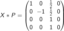
Do note that due the projection in the previous step, the translation here is a shear of the frustum. Thus if we multiply X and P we get:
And if we combine everything we get the complete projection matrix:
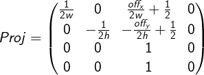
Note that z and w are identical, which is a bit unsual. Normally the projection matrix would map the z value into the device specific screen space z range (e.g. [-1,1], [0,1] or [0,0xFFFFFF]) but RW matrices only have 3 rows and we need the camera z value for the division. Hence RW stores zShift and zScale values in the RwCamera such that screen space z can be computed as zShift + zScale/zcam. This is equivalent to calculating zShift*zcam + zScale with the matrix and then dividing by w (= zcam). In fact, the Direct3D and OpenGL driver do just that.
Calculating zScale and zShift just involves solving some equations. I will abbreviate the near and far values in camera space as n and f, and as N and F in screen space. We want to map [n,f] to [N,F], so we plug in those values and get two equations: zScale/n + zShift = N and zScale/f + zShift = F. After solving this we get zScale = nf(N-F)/(f-n) and zShift = (Ff-Nn)/(f-n).